Installation Practices for Pressure Relief Valves
A pressure
relief valve is normally the primary component of overpressure protection systems. The associated inlet and outlet piping, regardless of PRV design, can determine the degree of safety provided and the quality of PRV performance.
Inlet Piping
The proper design of inlet piping to PRVs is extremely important. Very often, pressure relief valves are added to an installation at the most physically convenient location, with little regard to the effects of inlet pressure loss.
Pressure loss always occurs during flow in the pipe to a PRV inlet. Depending upon the size,
geometry, and inside surface condition (roughness) of the pipe, the pressure loss may be large (perhaps 10% or greater) or small (less than 3%).
API Recommended Practice RP 520, Part II, and non-mandatory ASME Section VIII, Appendix M, recommend a maximum inlet pressure loss of 3%. However, it is extremely vital to recognize that the mandatory part of ASME Section VIII does not place a limit on inlet pressure loss as long as the PRV relieves the required capacity and is operationally
stable!
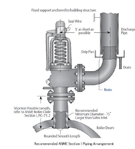
Outlet Piping
Outlet and inlet piping are equal in importance. Most Anderson Greenwood Crosby PRVs will perform better than other commercial valves when piping conditions are substandard.
Although it often appears that very little discharge piping is used for some valves — for example, one elbow and a short, vertical riser — significant built-up back pressure can be developed.
Almost all conventional PRVs will have reduced lift or reclose prematurely with as little as 10 to 15% built-up back pressure. This is known as chatter or flutter, which are very unfavorable conditions well known to you by now. For this reason, API and ASME recommend that discharge piping for conventional, unbalanced PRVs limit built-up back pressure to 10%.
It is suggested that you keep this rule in mind, although the Anderson Greenwood Types 81/83/86 designs can tolerate somewhat greater built-up back pressure than other designs. Further, lengthening the PRV blowdown setting can compensate for some built-up back pressure.
Valve Mounting Practices
There are some important considerations about the physical mounting of PRVs that will help ensure their proper performance. Let’s look at some of the more important ones.
Mount PRVs Vertically Upright
This seems too simple to mention, but unless the factory approves an alternate arrangement, all PRVs should be mounted with the inlet centerline in a vertical plane with the inlet facing down.
Pilot Operated PRVs should always be installed with the pilot in the upright and vertical orientation. This is the orientation of all PRV illustrations in Anderson Greenwood Crosby literature. Mounting a valve on its side or upside-down is poor practice and is in direct conflict with API, ASME and Anderson Greenwood Crosby recommendations.
Properly Support and Brace PRVs
All PRVs should be mounted in such a way that bending stresses are minimized. All ASME Code-stamped pressure relief valves are self contained, relying only on system pressure for operation. Bending stress can distort the internal parts and/or body increasing the resistance (friction) between the moving parts— especially in a direct spring operated valve.
Set pressure might then increase; wear and tear during a relief cycle may increase; or the stress could completely prevent valve closure. Bending stress may occur for three reasons:
1. Physical Load
The PRV may be supporting associated piping. To prevent this, the inlet and outlet piping should be independently supported.
2. Thermal Expansion
Until actuation, most PRVs are at ambient temperature. When they open, the fluid flow will eventually heat or cool the valve and adjacent piping.
This will result in expansion or contraction of the valve and companion piping. If the structural support restrains some flexing of the pipe, high stresses could possibly be imposed on the PRV.
3. Reactive Forces
These are developed whenever a PRV is relieving. This reaction comes from the flow of fluid through the valve, similar to the thrust from a rocket or jet engine as well as flow direction changes.
The thrust will produce bending stress on the valve and companion piping. This may be prevented by the installation of structural supports and bracing.
Storage and Handling
Until a PRV is installed, it should be kept in dry storage, away from contamination. This will prevent corrosion and entry of particulate matter, such as sand and insects. Anderson Greenwood Crosby will seal all openings and provide flange face protection as needed
as standard practice.
We can furnish special packaging for severe environments, such as ocean freight. Pressure relief valves are precision products, subject to loss in performance if mishandled. PRVs should not be dropped or subjected to shock, as this may distort the body and cause binding of moving parts.
Pilot operated pressure relief valves usually use external tubing and often a variety of accessories. Care should be taken during handling. Metal seated direct spring operated PRVs must be transported, and stored in the vertical, “upright”, position. The vertical position is required, to minimize any potential for damage of the seating surfaces.
Additional information for further study is available through the Anderson Greenwood Crosby technical seminars. For other application recommendations, refer to Advisor bulletins.
Standarts and References
Regulatory Body Codes and StandardsRegulatory Body Codes and Standards
Regulatory Body – Codes and Standarts
• American National Standards Institute (1430 Broadway New York, NY 10018)
- B16.34 Steel Valves, Flanged and Buttweld Ends
- B16.5 Steel Pipe Flanges and Flanged Fittings
- B31.1 Power Piping
- B31.3 Chemical Plant and Petroleum Refinery Piping
- B31.4 Liquid Petroleum Transportation Piping System
- B95.1 Terminology for Pressure Relief Devices
- ANSI/ASME PTC 25.3 Performance Test Code, Safety and Relief Valves
• American Petroleum Institute (2101 L Street Northwest Washington, DC 20037)
- API RP 510 Pressure Vessel Inspection Code
- API RP 520 Recommended Practice for the Design and
- Installation of Pressure Relieving Systems in Refineries:
- Part I - Design; Part II - Installation
- API RP 521 Guide for Pressure Relief and Depressuring Systems
- API Standard 526 Flanged Steel Safety Relief Valves
- API Standard 527 Commercial Seat Tightness of
- Safety Relief Valves with Metal to Metal Seats
- API Standard 2000 Venting Atmospheric and Low Pressure Storage Tanks
- API Guide for Inspection of Refinery Equipment
- Chapter XVI - Pressure Relieving Devices
• The American Society of Mechanical Engineers United Engineering Center (345 East 47th Street New York, NY 10017)
- Boiler and Pressure Vessel Code
- Section I - Power Boilers
- Section II - Materials
- Section IV - Heating Boilers
- Section VII - Care of Power Boilers
- Section VIII - Pressure Vessels
- Section IX - Welding and Brazing Qualifications
• International Organisation for Standardisation (Case Postale 56 CH-1211 Geneve 20, Switzerland)
- ISO-9000 Quality System
- ISO-4126 Safety Valves - General Requirements
• National Board of Boiler and Pressure Vessel Inspectors (1055 Crupper Avenue Columbus, OH 43229)
- NB-25 National Board Inspectors Code
- NB-65 National Board Authorization to Repair ASME and National Board Stamped Safety Valves and Relief
Valves
• National Association of Corrosion Engineers (P.O. Box 1499 Houston, TX 77001)
- NACEMR0175
Mehmet Berk Güven
Field Sales Engineer
Pressure Management
Emerson Automation Solutions