Abstract
This paper presents the capabilities of Finite Elements Micromechanical Analysis (FEMA) method for simulating mechanical behaviour of composite materials. A thermosetting prepreg composite system with unidirectional and cross-ply desginations are considered in this paper.
3-Dimensional Representative Volume Elements (RVEs) are built according to the fibre volume fraction of composite materials with a commercial finite elements programme.
These models enable to calculate the elastic properties of the composite materials with great accuracy. In addition to this, stress distributions within the fibres and the matrix can be investigated and give idea about where and how the damage can develop.
1.Introduction
Finite Elements Method (FEM) is a very popular method to predict the mechanical behaviour of materials. It is highly valuable since it can reduce experimental cost by providing an idea about the mechanical response of the regarding material.
Finite Elements Micromechanical Analysis (FEMA) method has been a very important numerical method to predict the mechanical behaviour of materials in micro-level for the last two decades.
There has been numerous studies performed by using this method. It can be applied easily by using any commercial finite elements programme.
Even though polymeric composite materials are mostly prefferred, different composites can be analysed with this method. It can provide important idea about the mechanical response of the regarding materials under different load modes in micro-level.
Simple geometrical models are used in FEMA where the fibres are packed into these geometries according to the fibre volume fraction of the regarding composite. Generally the fibres are packed into the models with respect to two geometries; square packed and hexagonally packed arrays as shown in Figure 1.
Two different materials should be defined in the graphical user interface of the commercial FE programme for the constituents and their properties must be known. One should be careful while entering the material properties.
Carbon or glass fibres should be defined as orthotropic or transversely isotropic, whereas matrix materials, polymeric resins, should be defined as isotropic.

Figure 1. Square and hexagonally packed RVEs.
In this paper, hexagonal and square packed RVEs are taken into consideration to investigate the mechanical behaviour of a carbon fibre reinforced thermosetting composite system with FEMA method. A commercial FE programme, ABAQUS® [1] is used for the analyses.
First the FEMA procedure in ABAQUS is described briefly. Then elastic properties of the composite are calculated with RVEs. Finally the results are compared with available data in literature.
It can be seen that the FEMA can provide good agreements with the experimental values and this proves the efficiency of this method by using simple models and low computational time in terms of predicting mechanical response of composite materials.
2.Micromechanical Model
2.1. Representative Volume Elements and Boundary Conditions
Meshed RVEs can be seen in Figure 2. These RVEs can be reduced to simpler geometries, shown with black lines in Figure 2. In order to provide periodicity and symmetry, unified or periodic boundary conditions [2, 3] should be applied to the model.
Basically, the requirements for the periodic boundary conditions are given in Equations 1-3. Application of these boundary conditions is very easy in ABAQUS graphical user interface by using symmetric boundary conditions and the “Equation Type” constraints.
Definitions of boundary conditions in ABAQUS for different load conditions are given in Table 1 and Table 2 capital letters. (X,Y,Z) on the left side of the tables designate the normal direction of planes whereas small letters on top, (x,y,z) show the directions of the nodes.
The material in consideration is a thermosetting prepreg composite system which is a carbon fibre reinforced epoxy matrix, having 57.4% fibre volume fraction. This material system is chosen since the open literature can provide comparison.

Figure 2. RVEs used in this study.
uz (TOP)-uz (BOTTOM)=0 (1)
uy (RIGHT)-uy (LEFT)=0 (2)
ux (FRONT)-ux (BACK)=0 (3)
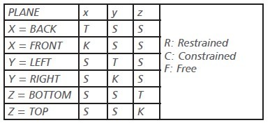
Table 1. Boundary conditions for normal loading

Table 2. Boundary conditions for shear loading
2.2. Calculation of Elastic Properties
Composite materials have five mechanical elastic constants. They are listed in Table 3. Even though there are six independent parameters given in Table 3, transverse shear modulus, G23, can be obtained by using the other parameters as shown in Equation 4.
A unit strain is applied in regarding direction to provide deformation and the average of the resulting stresses in the model is equal to that elastic modulus. Three steps are followed to calculate the regarding elastic moduli:i. “Equation type” constraint sums the stresses in each surface node to a single node in terms of reaction force.
The regarding reaction force is noted first, ii. The reaction force in that single node is divided to regarding surface area. iii. Then, Hooke’s law is applied to calculate that elastic property. Since the applied strain is unit, equal to 1, the calculated stress in (ii) is the elastic modulus in regarding direction.
Table 3. Elastic constants of composite materials

 3.Results and Discussion
The resulting deformations caused by the application of unit strain under each load modes are shown in Figure 3. Only hexagonal models are presented for unidirectional model in Figure 2.
Because, even though the square model has advantage in terms of simpler geometry, that model cannot provide to obtain the transverse isotropy relation in Equation 4. Because of this, the resulting stress distributions under transverse shear loading is not accurate.
It can be seen that the resulting stress distributions are different under each unit strains in Figure 3. The average stress values shown in the legends of each load conditions correspond to the regarding elastic modulus.
Their calculated elastic properties and their comparison with the literature is shown in Table 4. Results show that the FEMA method can provide good correlations with the experimental results. Thus, it is a simple and efficient numerical method for predictions of mechanical behaviour of materials as shown in Figure 3 and Table 4.
Although, only the calculation of elastic moduli values with FEMA is included in this paper. The capabilities of this method is not limited to this only. The process-induced residual stresses, and the effect of residual stresses to the strength of the material can be investigated with FEMA.
The detailed studies regarding the application of FEMA for prediction of process-induced residual stresses, and to progressive damage analysis of composites under the subsequent loading can be found in literature [4–7] or the readers who have interest to this subject can get in contact with the authors.

Figure 3. Resulting deformations and stress distributions under different load modes

Table 4. Comparison of elastic moduli values with test results
4. Conclusion
This paper summarizes the capabilities of Finite Elements Micromechanical Analysis (FEMA) method which can predict the mechanical behaviour of composite materials in micro level.
A thermosetting prepreg composite system with unidirectional and cross-ply desginations are investigated with square and hexagonally packed RVEs. It is seen that the FEMA method provides good predictions for elastic moduli values.
They are validated by comparing with test results. FEMA results can also present stress distributions within the fibres and the matrix under different load modes that can give idea about where and how damage can develop.
This method can be adopted for investigation of proces-induced residual stresses and its effect during progressive damage analysis.
 Dr. Fatih Ertuğrul Öz
Department of Mechanical Engineering
Faculty of Engineering
Boğaziçi University
Project Leader
Dr. Fatih Ertuğrul Öz
Department of Mechanical Engineering
Faculty of Engineering
Boğaziçi University
Project Leader
 Prof. Dr. Nuri Ersoy
Department of Mechanical Engineering
Faculty of Engineering
Boğaziçi University
Design and Mathematics
Faculty of Engineering University of West of England
Prof. Dr. Nuri Ersoy
Department of Mechanical Engineering
Faculty of Engineering
Boğaziçi University
Design and Mathematics
Faculty of Engineering University of West of England
5. References
1. Abaqus 6.14, “Documentation.” Dassault Systèmes, 2014, 2014.
2. Xia, Z., Y. Zhang, and F. Ellyin, “A unified periodical boundary conditions for representative volume elements of composites and
applications”, International Journal of Solids and Structures, Vol. 40, No. 8 pp. 1907–1921, 2003.
3. Ersoy, N., T. Garstka, K. Potter, M. R. Wisnom, D. Porter, M. Clegg, and G. Stringer, “Development of the properties of a carbon
fibre reinforced thermosetting composite through cure”, Composites Part A: Applied Science and Manufacturing, Vol. 41, No. 3 pp.
401–409, 2010.
4. Oz, F. E., Micromechanical Progressive Damage Model for Predicting Resin Dominated Strength Values of Fibre Reinforced
Composites Under Various Types of Loading, Yüksek Lisans Tezi, Boğaziçi University, 2012.
5. Ersoy, N. and F. E. Oz, “Micromechanical Investigation of Residual Stresses and Strength of Cross-Ply Laminates,” ICCM 19 -
Proceedings of the 19th International Conference on Composite Materials, Montreal - Canada, 2013.
6. Oz, F. E. and N. Ersoy, “Acoustic Emission Analysis for Validation of Micro Mechanical Models,” ICCM 2015 - Proceedings of
the 20th International Conference on Composite Materials, Copenhagen - Denmark, 2015.
7. Oz, F. E., Characterisation of Failure in Composite Materials with Acoustic Emission and Correlation with Micromechanics,
Doktora Tezi, Boğaziçi University, 2018.
8. Marlett, K., Y. Ng, and J. Tomblin, “Hexcel 8552 AS4 Unidirectional Prepreg at 190 gsm & 35 % RC Qualification Material
Property Data Report”, Niar - Wichita State University, 2011.