Abstract
Fiber composites have been in use since the 1960s. The use of this technology is quite wide. Many old reinforced concrete structures show corrosion and corrosion of steel reinforcement. Generally, it is cheaper to retrofit these structures instead of demolishing them again.
The same applies to structures whose intended use has been altered and subjected to higher loads. From 1975 to the present day, it has been observed that composites are used especially in the outer body of buses.
The composites used herein are fiber-reinforced materials with polyester binders. Generally, a reduction in weight of a commercial vehicle resulting from composite use is around 10%, which provides an advantage of 5-10% in fuel consumption. The degree of fiber reinforcement depends on the absence of superficial voids.
Thus, the theoretical situation can be approached. It should be shorter than a certain critical length depending on the diameter of the fibers and the nature of the adhesion force with the matrix.
In these composites, the second phase embedded in the metal matrix may be in the form of continuous fibers or may be in the form of finely distributed small particles. The most important factor limiting the widespread use of laminated composite materials is; complex damage mechanism.
These types of damage often occur interactively with one another and affect the material’s resistance to loads. The impact to which a layered composite material may be classified can be classified into three types. The pulse with low energy, the pulse with high energy, and the pulse with the highest energy compared to others.
Especially for unmanned aircraft (UAV), satellite and space vehicles, signal processing/computing circuits and devices, high temperature (600oC and above), impact and radiation environment to allow the safe operation, while reducing the volume and weight of composite materials to develop various simulation studies are summarized in this study.
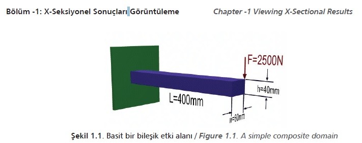
The aim of the example shown in Figure 1.1 is to outline the steps required to view cross sectional results such as deformation and stress.
1.2. Preprocessing Steps
• Creating block (dimensions),
• Defining the type of element (2d-3d),
• Defining the element material properties (e.g. young’s modulus, poisson’s ratio),
• Defining the mesh size (e.g. elements size of 20 mm),
• Meshing the volume.
1.3. Solution
• Defining the analsysis type (e.g. static),
• Applying constraints (e.g. on areas),
• Applying loads (e.g. on keypoints),
• Solving the system.
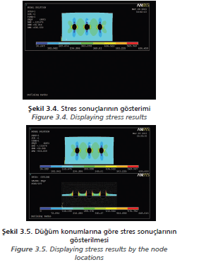
1.4. Postprocessing: Viewing the Results


2.1. Postprocessing: Defining the Problem
• Defining key points for the keypoint 1 as (0,0), and keypoint 2 as (400,0),
• Creating a line joining keypoints 1 and 2,
• Defining real constants for the area as 2400, area moment of inertia as 320e+03, and total beam height as 40,
• Defining element material properties for the young’s modulus as 200000, and poisson’s ratio as 3.0,
• Defining mesh size for an element edge length of 20 mm.
2.2. Defining Rectangular Areas and Creating Circles
• Defining 2 corners,
• A rectangle has (0, 0), Width= 200, Height=100,
• Creating solid circles,
• For Circle 1 X= 50, Y= 50, Radius= 10,
• For Circle 2 X= 100, Y=50, Radius=10,
• For Circle 3 X= 150, Y=50, Radius=10.


3.2. After Subtracting the Circles
• Defining type of element; translation along the X and Y axis,
• Defining real constants, entering 10 as a thickness,
• Defining element material properties as linear, elastic and isotropic,
• For the composite young’s modulus ad 200000 and poisson’s ratio as 3.0,
• Defining mesh size as 5 mm of an element edge,
• Meshing the entire areas,
• Applying loads as -2500 N on keypoint 2.
3.3. Solution Phase: Assigning Loads and Solving
• Defining analysis type as static,
• Applying constraints as displacement and on lines in structural,
• Applying loads as pressure and on lines in structural and applying uniform pressure constant as -200 on the top of the area.
Cemil Koyunoğlu - Yalova Üniversitesi / Yalova University - Mühendislik Fakültesi / Faculty of Engineering - Enerji Sistemleri Mühendisliği Bölümü Department of Energy Systems Engineering