Effect of Composite Material on Rotor Dynamics
In jet engines, General Electric is focused on the development and use of durable, advanced, and lightweight special coatings and composite materials. However, General Electric has produced an axial-flow, twin-rotor, high-bypass turbofan jet engine called the Next Generation (GEnx). This product is derived from the GE90 family.
This product was introduced in 2007 for the Boeing 787, and the Dreamliner, to replace the CF6 in their respective product lines. GEnx carries composite technology from the GE90 family. A composite fan case, 18 composite fan blades, and titanium aluminide
stages 6 and 7 low-pressure turbine blades were used to manufacture the GEnx. Weight reduction due to the use of lightweight composite materials provides a 15%
improvement in specific fuel consumption compared to CF6.
The GEnx can achieve a high BPR of 9.0:1 and a massive OPR of 58.1:1 thanks to the 10-stage HP compressor powered by more efficient, larger fan blades. In this article, an example application is given to examine the effect of composite material on the rotor with the application of industry 4.0, which is a new field.
1. Introduction
The cylinder shown in the figure in the 3D geometric model created using Ansys-Fluent gives the boundaries of the air flowing around the fan.
[caption id="attachment_133616" align="aligncenter" width="448"]
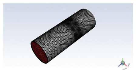
Figure 1. Image of a (possible) rotor meshes with composite casting.[/caption]
[caption id="attachment_133617" align="aligncenter" width="519"]
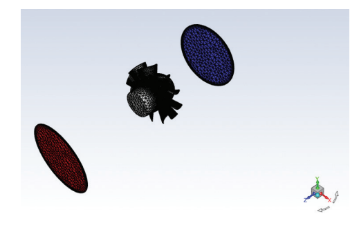
Figure 2. Mesh view for determining the rotational force of the rotor (metal cast) in the middle of a composite cast horizontal fan.[/caption]
[caption id="attachment_133618" align="aligncenter" width="506"]
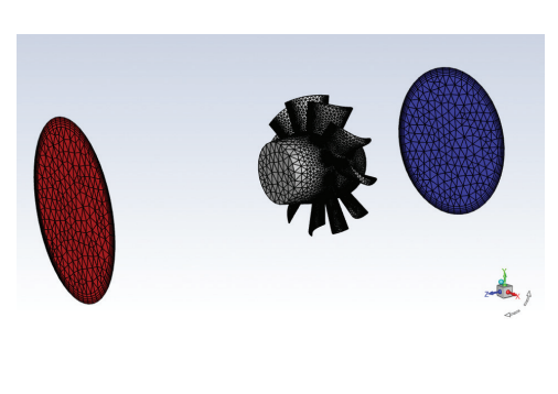
Figure 3. Zoom mesh view of rotor and fan block.[/caption]
After determining the k-e (realizable) and “scalable wall” of the viscous model to be applied, the density value for the air flowing from the red and blue regions of Figure 3 is entered as 1.2 kg/m3. The rotor speed is as small as 300 rpm. Air inlet (blue zone) velocity of 1.2 m/s.
2. Results
The results obtained in 2100 iterations are given below.
[caption id="attachment_133619" align="aligncenter" width="663"]
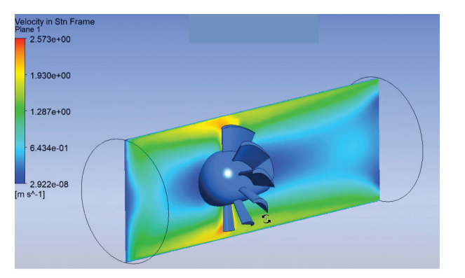
Figure 4. Representation of velocity distribution on the axis of symmetry.[/caption]
As can be seen from Figure 4, it is seen that the velocity distribution is directly dependent on the rotor rotation speed in the blade design. The decrease in the rotor
weight depending on the rotation speed increases the energy required for the torque. The use of lightweight composites at a rotor speed of 300 rpm significantly affects the energy requirement for rotor rotation. For more detailed solutions to our article, you can write to my contact information. I wish you all healthy and happy days.
Dr. Cemil Koyunoğlu
Yalova University
Faculty of Engineering
Department of Energy Systems Engineering